Written by Stefan Nikolaj
11 Aug 2022
The convenience of modules
Sometimes, when on vacation in a Central/Western European country, I visit hobbyist electronics stores. I’m always amazed at how many electronics modules there are for any purpose. Need a negative voltage rail? Just buy a module, connect three wires, and you never need to know what inverting buck/boost converters are. However, understanding how they work is necessary if there ever is a need to troubleshoot them. Once I ordered a display module from Aliexpress, however it had a defect in the form of a misplaced SOT-23-3 voltage regulator, which lowered the supply voltage from 5V to 3.3V. I attempted to solder it back in, however somehow the plastic package just melted. Luckily, I knew what the components did, and could just bridge the necessary pins to make it work, even though 5V tolerance would be lost.
This gave me the idea of making my own modules, which would have the functionality of commercial ones, while being a custom design. This led me to learning about PCB design and getting a successful professional-looking module done, which is a story for another day. For today, I want to discuss a module I built that is a 7 segment display driver. It’s something I realized I didn’t know I needed, after I used a Chinese TM1637-based module, which was much more convenient than connecting regular 7 segment displays. However, the TM1637 has a custom protocol that looks like I2C, but is different enough to be completely incompatible. It requires using pre-made libraries, as the datasheet is brief and cryptic, meaning that it’s hard to get the protocol right in a short time. The actual module is used in a previously-documented project, the PIC thermometer.
From this came the idea of building my own display driver module, especially as I had bought a bag of 25 assorted 7 segment displays from a hobby electronics store in Austria, Neuhold Electronics. If I had a universal driver design, it would mean that using these displays would be as easy as just changing the pinout appropriate for the number of digits. However, the fact that they had different pinouts would mean that the planning phase would require some thought. From here began my design.
Microcontroller choices…
Initially, my biggest issue was finding what microcontroller I would use. My first requirement was that the whole array of chips necessary would be in DIP form. I have a discrete 7 segment display driver design with all DIP chips, however it uses 5 ICs, some of which are quite rare, and is generally too complex to be used on a larger scale. Many microcontrollers I found had the same issue – they were either way too limited in pin count, or were too complex, thus too expensive to be applied on a larger scale. Since I wanted cheap and available microcontrollers, I decided an 8-bit one would be enough. As part of a project I’m doing, I currently have a bunch of 8051s, which are almost ideal in terms of simple, cheap and small chips for driving LEDs. With a 4-digit, 7 segment display, using multiplexing only 11 IO pins are needed, which most 8051 derivatives have. From this, from the choices of the AT89C4051 and AT89S52, the former won, as it was smaller, cheaper and I had more of them on hand.
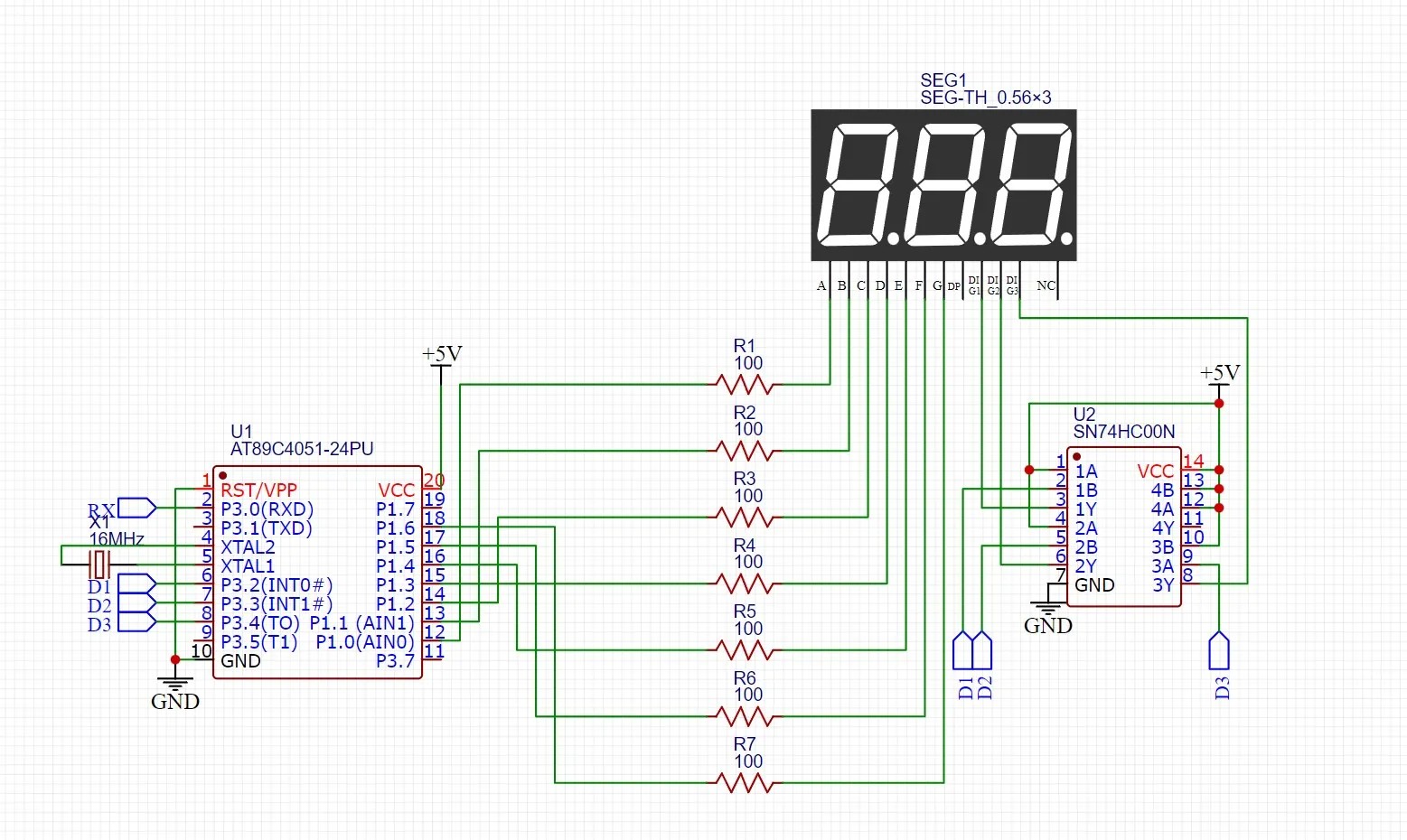
The biggest issue with 8051s in terms of driving LEDs, though, is the fact that they can only sink significant current, not source it. This means that an external way to source current is necessary. From my choice of a common cathode display, using multiplexing, for a 4-digit design, I would only need 4 separate current sources. Doing some experimentation with the displays, I decided that a 5V supply with a 100 ohm resistor would give sufficiently bright LEDs for most cases. With an assumed voltage drop of 2V, through Ohm’s law it can be calculated that 30mA are going through each resistor. With 7 segments, this means that a total 210mA are needed, with the microcontroller’s current requirements being negligible. However, if the displays are being multiplexed, that current is divided by the number of digits. Thus, for a 3-digit display, only 210/3 = 70mA are needed per current source.
LED control is actually quite complex?!
Generally, for these purposes, there are go-to solutions, such as the ULN2003 Darlington array, or a discrete transistor solution. However, I decided against these, as I have no way of sourcing ULN2003s where I live, and at the moment I don’t have any transistors. However, one thing I do have are 30+ clone SN74HC00 NAND-gates on hand. In the datasheet it is visible that their output stage is a push-pull MOSFET configuration, and by tying their inputs together, each gate can be used as a simple inverting buffer. This was ideal for me, with the only caveat being that the absolute maximum continuous current per NAND-gate is 25mA, almost three times less than the required current. After some deliberation, I decided to follow this approach, with some testing on how stable the configuration is.

Protocol design!
The code for the microcontroller came out to be the most interesting part of the journey. My requirements were a universal interface, and a microcontroller which could adjust, on the fly, how many segments it’s controlling. The interface would also have to be simple, as I would be using this module to test any retro computers I’m building. Commands would have to be short and be able to pack a lot of information in one, while also being able to store a configuration in ROM, without having to generate it on-the-fly.
The first thing I would have to deal with was how data would get into the microcontroller, but the AT89C4051 made this easy for me. As I had to use 10 pins for the LEDs, I had only 5 more remaining, meaning a parallel interface was not doable. The only other interface the AT89C4051 has is UART, and by having a bunch of 16MHz crystals I just decided to go with a 9600 baud UART interface as the physical layer of my protocol, but it is physical-layer-agnostic. Next I had to deal with how the microcontroller would decode incoming bytes into commands.
It was at this moment that inspiration came from another type of display – the famous 16x2 HD44780-based display, coupled with the realization that with any 8-bit communication, I would only need a maximum of 7 bits to send information about a segment. The remaining bit could be used to indicate whether the byte was data or command, like with the 16x2 displays. I then also realized that the simplicity of the display type meant that I could pack a lot of information in one command packet, and I came up with the following design for the command byte:
| B7 | B6 | B5 | B4 | B3 | B2 | B1 | B0 |
|---|---|---|---|---|---|---|---|
| Command/Data (0/1) | Data byte format (1 for ROM, 0 for custom digit) | Reserved bit | Digit on/off (1/0) | Number of digits (upper bit) | Number of digits (lower bit) | Digit selected (upper bit) | Digit selected (lower bit) |
The data byte, depending on bit 6 from the last command byte, either sends an entire digit or a 4-bit BCD code (lower nibble of data byte) corresponding to a digit stored in ROM, with hexadecimal digits also being available. The actual values used for all the available digits are:
const uint8_t digitArray[] = {
    0b0111111, // 0
    0b0000110, // 1
    0b1011011, // 2
    0b1001111, // 3
    0b1100110, // 4
    0b1101101, // 5
    0b1111101, // 6
    0b0000111, // 7
    0b1111111, // 8
    0b1101111, // 9
    0b1110111, // A
    0b1111100, // b
    0b0111001, // C
    0b1011110, // d
    0b1111001, // E
    0b1110001, // F
};
This simple protocol turned out to work perfectly, with the hardest part of the whole microcontroller code being the multiplexing and dealing mentally with all the inverting that happened. Unfortunately, the code turned out quite ugly, but was very fast:
void writeDigit(uint8_t digitSelect){
    P3 |= 0b00111100; // blank display
    if(isOn){
        P1 = 0b11111111; // disable pin OE, zero out all other pins to work with the OR
        P1 ^= digitValue[digitSelect]; // set P1 to the digit without upsetting P1.7
        P3 = (P3 & 0b11000011) | (((1 << (digitSelect)) ^ 0b1111) << 2); // set middle nibble of P3 to select digit
    }
}
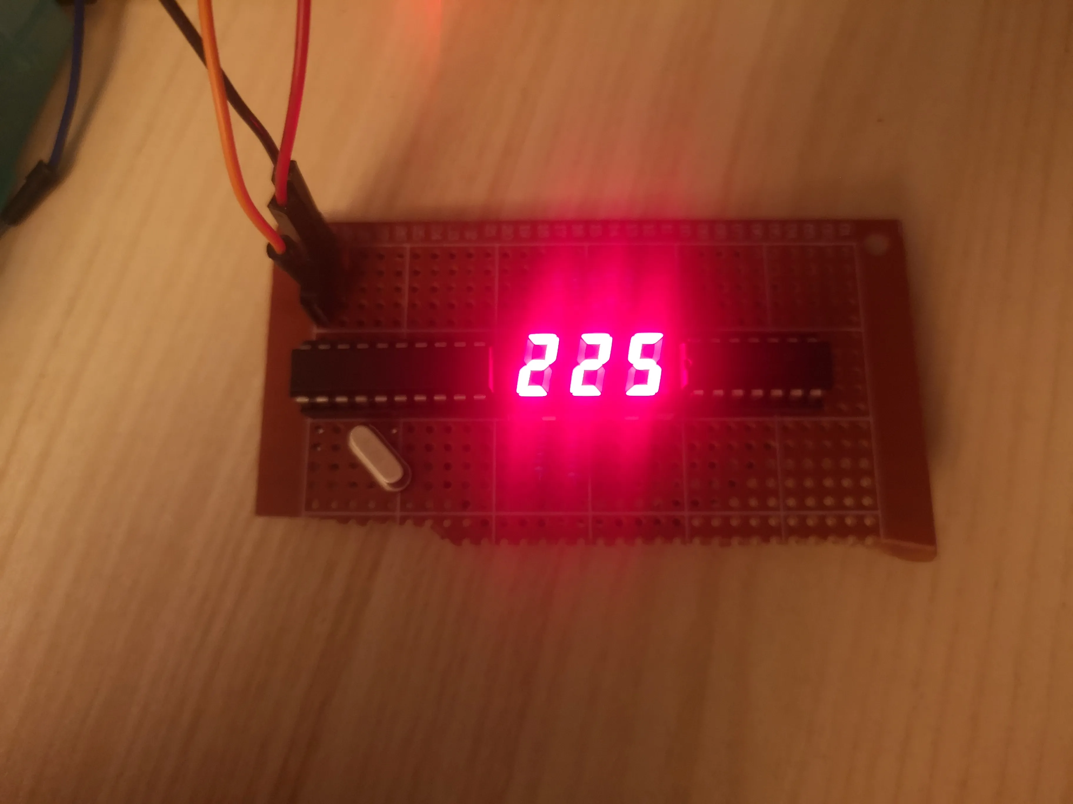
I built the circuit on a perfboard, and powering it up with the microcontroller worked from the first try. The digits were very bright, and after a couple of hours of having the SN74HC00 turned on for way past the maximum allowed current, the digits were working and as bright as when I first turned them on. The chip itself provides some current limiting by itself, and the popular YouTuber Ben Eater, which uses logic gate chips to build massive circuits, even uses them to drive LEDs without current to save on board space. I’m perfectly fine with this configuration, and the 74HC00s are only slightly warmer than ambient, which I have no issue with. I have many more to replace it with anyways. However, I must note that if I was building a reliable circuit, something that would have to run continuously for a long time and be reliable, and was not for myself, I would use something more suited to this job, like PNP transistors.

